Friday, January 14, 2011

Converting A.c. to D.c.

Diodes


Circuit symbol:


Diodes are kinds of device that allow current flow only in one direction in circuits. (The arrow of the circuit symbol shows the direction in which the current can flow.) Thus, only half of the cycles of alternating current can pass from the diodes. You can easily convert alternating current into the direct current with this device. Diodes are the electrical version of a valve and early diodes were actually called valves.

Following circuit shows the usage of diodes.

In the given circuit, D1 let current flow however, D2 does not let current flow.


Forward Voltage Drop

Electricity uses up a little energy pushing its way through the diode, rather like a person pushing through a door with a spring. This means that there is a small voltage across a conducting diode, it is called the forward voltage drop and is about 0.7V for all normal diodes which are made from silicon. The forward voltage drop of a diode is almost constant whatever the current passing through the diode so they have a very steep characteristic (current-voltage graph).

Reverse Voltage

When a reverse voltage is applied a perfect diode does not conduct, but all real diodes leak a very tiny current of a few µA or less. This can be ignored in most circuits because it will be very much smaller than the current flowing in the forward direction. However, all diodes have a maximum reverse voltage (usually 50V or more) and if this is exceeded the diode will fail and pass a large current in the reverse direction, this is called breakdown.

Ordinary diodes can be split into two types: Signal diodes which pass small currents of 100mA or less and Rectifier diodes which can pass large currents. In addition there are LEDs and Zener diodes


Rectifier diodes (large current)

Rectifier diodes are used in power supplies to convert alternating current (AC) to direct current (DC), a process called rectification. They are also used elsewhere in circuits where a large current must pass through the diode.

All rectifier diodes are made from silicon and therefore have a forward voltage drop of 0.7V. The table shows maximum current and maximum reverse voltage for some popular rectifier diodes. The 1N4001 is suitable for most low voltage circuits with a current of less than 1A.


Zener diodes


Circuit symbol:


Zener diodes are used to maintain a fixed voltage. They are designed to 'breakdown' in a reliable and non-destructive way so that they can be used in reverse to maintain a fixed voltage across their terminals. The diagram shows how they are connected, with a resistor in series to limit the current.

Zener diodes can be distinguished from ordinary diodes by their code and breakdown voltage which are printed on them. Zener diode codes begin BZX... or BZY... Their breakdown voltage is printed with V in place of a decimal point, so 4V7 means 4.7V for example.

Zener diodes are rated by their breakdown voltage and maximum power:

  • The minimum voltage available is 2.4V.
  • Power ratings of 400mW and 1.3W are common.


Bridge rectifiers

There are several ways of connecting diodes to make a rectifier to convert AC to DC. The bridge rectifier is one of them and it is available in special packages containing the four diodes required. Bridge rectifiers are rated by their maximum current and maximum reverse voltage. They have four leads or terminals: the two DC outputs are labelled + and -, the two AC inputs are labelled ~.

The diagram shows the operation of a bridge rectifier as it converts AC to DC. Notice how alternate pairs of diodes conduct.


Cathode Ray Oscilloscope

The cathode-ray oscilloscope (CRO) is a common laboratory instrument that provides accurate time and aplitude measurements of voltage signals over a wide range of frequencies. Its reliability, stability, and ease of operation make it suitable as a general purpose laboratory instrument. The heart of the CRO is a cathode-ray tube shown schematically in Fig. 1.


The cathode ray is a beam of electrons which are emitted by the heated cathode (negative electrode) and accelerated toward the fluorescent screen. The assembly of the cathode, intensity grid, focus grid, and accelerating anode (positive electrode) is called an electron gun. Its purpose is to generate the electron beam and control its intensity and focus. Between the electron gun and the fluorescent screen are two pair of metal plates - one oriented to provide horizontal deflection of the beam and one pair oriented ot give vertical deflection to the beam. These plates are thus referred to as the horizontal and vertical deflection plates. The combination of these two deflections allows the beam to reach any portion of the fluorescent screen. Wherever the electron beam hits the screen, the phosphor is excited and light is emitted from that point. This coversion of electron energy into light allows us to write with points or lines of light on an otherwise darkened screen.

In the most common use of the oscilloscope the signal to be studied is first amplified and then applied to the vertical (deflection) plates to deflect the beam vertically and at the same time a voltage that increases linearly with time is applied to the horizontal (deflection) plates thus causing the beam to be deflected horizontally at a uniform (constant> rate. The signal applied to the verical plates is thus displayed on the screen as a function of time. The horizontal axis serves as a uniform time scale.

The linear deflection or sweep of the beam horizontally is accomplished by use of a sweep generator that is incorporated in the oscilloscope circuitry.

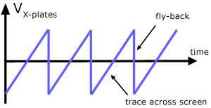
The voltage output of such a generator is that of a sawtooth wave as shown in Fig. 2. Application of one cycle of this voltage difference, which increases linearly with time, to the horizontal plates causes the beam to be deflected linearly with time across the tube face. When the voltage suddenly falls to zero, as at points (a) (b) (c), etc...., the end of each sweep - the beam flies back to its initial position. The horizontal deflection of the beam is repeated periodically, the frequency of this periodicity is adjustable by external controls.


CRO Operation:

A simplified block diagram of a typical oscilloscope is shown in Fig. 3. In general, the instrument is operated in the following manner. The signal to be displayed is amplified by the vertical amplifier and applied to the verical deflection plates of the CRT. A portion of the signal in the vertical amplifier is applied to the sweep trigger as a triggering signal. The sweep trigger then generates a pulse coincident with a selected point in the cycle of the triggering signal. This pulse turns on the sweep generator, initiating the sawtooth wave form.

The sawtooth wave is amplified by the horizontal amplifier and applied to the horizontal deflection plates. Usually, additional provisions signal are made for appliying an external triggering signal or utilizing the 60 Hz line for triggering. Also the sweep generator may be bypassed and an external signal applied directly to the horizontal amplifier.

CRO Controls

The controls available on most oscilloscopes provide a wide range of operating conditions and thus make the instrument especially versatile. Since many of these controls are common to most oscilloscopes a brief description of them follows.

Measurements of Voltage:

Consider the circuit in Fig. 4(a). The signal generator is used to produce a 1000 hertz sine wave. The AC voltmeter and the leads to the verticle input of the oscilloscope are connected across the generator's output. By adjusting the Horizontal Sweep time/cm and trigger, a steady trace of the sine wave may be displayed on the screen. The trace represents a plot of voltage vs. time, where the vertical deflection of the trace about the line of symmetry CD is proportional to the magnitude of the voltage at any instant of time.


To determine the size of the voltage signal appearing at the output of terminals of the signal generator, an AC (Alternating Current) voltmeter is connected in parallel across these terminals (Fig. 4a). The AC voltmeter is designed to read the dc "effective value" of the voltage. This effective value is also known as the "Root Mean Square value" (RMS) value of the voltage.

The peak or maximum voltage seen on the scope face (Fig. 4b) is Vm volts and is represented by the distance from the symmetry line CD to the maximum deflection. The relationship between the magnitude of the peak voltage displayed on the scope and the effective or RMS voltage (VRMS) read on the AC voltmeter is

VRMS = 0.707 Vm (for a sine or cosine wave).

Thus,
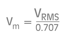


Agreement is expected between the voltage reading of the multimeter and that of the oscilloscope. For a symmetric wave (sine or cosine) the value of Vm may be taken as 1/2 the peak to peak signal Vpp

The variable sensitivity control a signal may be used to adjust the display to fill a concenient range of the scope face. In this position, the trace is no longer calibrated so that you can not just read the size of the signal by counting the number of divisions and multiplying by the scale factor. However, you can figure out what the new calibration is an use it as long as the variable control remains unchanged.

For more information on CRO and measurement of voltage, Visit:
Schoolphysics.co.uk
vsagar.com

Friday, January 7, 2011

Electromagnetic Induction


Electromagnetic Induction

Electromagnetic induction is the production of voltage across a conductor moving through a magnetic field. It underlies the operation of generators, all electric motors, transformers, induction motors, synchronous motors, solenoids, and most other electrical machines.

Michael Faraday is generally credited with the discovery of the induction phenomenon in 1831 though it may have been anticipated by the work of Francesco Zantedeschi in 1829.[citation needed] Around 1830[1] to 1832[2] Joseph Henry made a similar discovery, but did not publish his findings until later.

Laws of electromagnetism

Faraday's laws

English scientist Michael Faraday proposed three laws of electromagnetic induction:

(1) a changing magnetic field induces an electromagnetic force in a conductor;

(2) the electromagnetic force is proportional to the rate of change of the field;

(3) the direction of the induced electromagnetic force depends on the orientation of the field.

Lenz's law

The direction of an electromagnetically-induced current (generated by moving a magnet near a wire or by moving a wire in a magnetic field) will be such as to oppose the motion producing it.

This law is named after the German physicist Heinrich Friedrich Lenz (1804–1865), who announced it in 1833.


Alternate Current

Alternating Current is the movement of electrons in a wire backwards then forwards repeatedly and thus whose current constantly changes direction.In Europe this change repeats 50 times per second (or 50 Hz). In the USA, the frequency is 60 Hz.

AC is remarkably useful because it allows us to change electricity very easily using transformers which cannot work with DC.

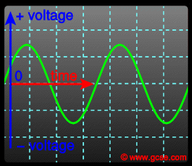
The UK mains supply is about 230V. It has a frequency of 50Hz (50 hertz), which means that it changes direction and back again 50 times a second. The diagram shows an oscilloscope screen displaying the signal from an AC supply.


Alternate Current Generators

Regardless of size, all electrical generators, whether dc or ac, depend upon the principle of magnetic induction. An emf is induced in a coil as a result of

(1) a coil cutting through a magnetic field, or
(2) a magnetic field cutting through a coil.

As long as there is relative motion between a conductor and a magnetic field, a voltage will be induced in the conductor.

That part of a generator that produces the magnetic field is called the field.
That part in which the voltage is induced is called the armature.

For relative motion to take place between the conductor and the magnetic field, all generators must have two mechanical parts - a rotor and a stator. The ROTor is the part that ROTates; the STATor is the part that remains STATionary. In a dc generator, the armature is always the rotor. In alternators, the armature may be either the rotor or stator.


Making AC electricity

When a wire is moved in the magnetic field of a generator, the movement, magnetic field and current are all at right angles to each other. If the wire is moved in the opposite direction, the induced current also moves in the opposite direction.

Remember that one side of a coil in a generator moves up during one half turn, and then down during the next half turn.

This means that as a coil is rotated in a magnetic field, the induced current reverses direction every half turn. This is called alternating current (AC).

It is different from the direct current (DC) produced by a battery, which is always in the same direction.


In practical generators, the coil is fixed, and mounted outside the magnet, and it is the magnet which moves.

The size of the induced voltage can be increased by:

* rotating the coil or magnet faster
* using a magnet with a stronger magnetic field
* having more turns of wire in the coil
* having an iron core inside the coil

The mains electricity is an AC supply. The voltage it supplies to our homes is 230V.


Transformers

A transformer is an electrical device that changes the voltage of an ac supply. A transformer changes a high-voltage supply into a low-voltage one, or vice versa.

* A transformer that increases the voltage is called a step-up transformer.
* A transformer that decreases the voltage is called a step-down transformer.
* Step-down transformers are used in mains adapters and rechargers for mobile phones and CD players.
* Transformers do not work with dc supplies.

A transformer consists of a pair of coils wound on an iron core. The AC in one coil produces a changing magnetic field. This changing magnetic field induces a voltage in the other coil of the transformer.

How transformers work

A transformer needs an alternating current that will create a changing magnetic field. A changing magnetic field also induces a changing voltage in a coil. This is the basis of how a transformer works:

  • The primary coil is connected to an AC supply.
  • An alternating current passes through a primary coil wrapped around a soft iron core.
  • The changing current produces a changing magnetic field.
  • This induces an alternating voltage in the secondary coil.
  • This induces an alternating current (AC) in the circuit connected to the secondary coil.

It's important to know that:

  • There is no electrical connection between the primary and the secondary coils.
  • Transformers only work if AC is supplied to the primary coil. If DC was supplied, there would be no current in the secondary coil.
  • As the current in the primary coil increases steadily or decreases steadily, there is a constant voltage induced in the secondary coil.
  • As the voltage in the primary coil reaches maximum strength the voltage induced in the secondary coil is at its weakest (zero volts).

Calculating voltages

The ratio between the voltages in the coils is the same as the ratio of the number of turns in the coils.

primary voltage / secondary voltage = turns on primary / turns on secondary

This can also be written as:

Vp/Vs = Np/Ns

Step-up transformers have more turns on the secondary coil than they do on the primary coil.

Step-down transformers have fewer turns on the secondary coil than they do on the primary coil.


Question

A transformer has 20 turns on the primary and 400 on the secondary. What is the output voltage if the input voltage is 500V?

Answer:

Vp/Vs = Np/Ns Therefore Vs/Vp = Ns/Np

Vs/500 = 400/20

Vs = 500 x (400/20)

Vs= 10,000 Volts


Ideal power equation

If the secondary coil is attached to a load that allows current to flow, electrical power is transmitted from the primary circuit to the secondary circuit. Ideally, the transformer is perfectly efficient; all the incoming energy is transformed from the primary circuit to the magnetic field and into the secondary circuit.

If this condition is met, the incoming electric power must equal the outgoing power:


giving the ideal transformer equation


Transformers normally have high efficiency, so this formula is a reasonable approximation.

If the voltage is increased, then the current is decreased by the same factor. The impedance in one circuit is transformed by the square of the turns ratio.[29]

For example, if an impedance Zs is attached across the terminals of the secondary coil, it appears to the primary circuit to have an impedance of (Np/Ns)2Zs. This relationship is reciprocal, so that the impedance Zp of the primary circuit appears to the secondary to be (Ns/Np)2Zp.


Transmission

Electricity is generated on a large scale at power stations and then transmitted through cables (called the National Grid) to factories and homes.

Copper cables carrying the electricity are buried in the ground or aluminium cables are suspended from pylons. Aluminium is used because it has a low density
and can safely be suspended from inexpensive thin pylons. Pylons have the disadvantage that they look ugly on the landscape but have the advantage of easy access to the cables for maintenance and repair. Transmission using pylons is cheaper than burying cables underground.

Transformers are used to produce a very high voltage for the transmission of electricity, to minimize energy loss.

A generator at a power station might produce electricity with a voltage of 25,000V and a current of 8,000A.

Such a large current would cause the cables of the National Grid to get hot because of the heating effect of current.

Energy could be lost due to :

1. heat loss due to resistance in coils
2. leakage of magnetic field lines between primary and secondary coils
3. heat loss due to eddy currents induced in iron core
4. hysteresis loss caused by the flipping of magnetic dipoles in the iron core due to the a.c.

To reduce the energy loss, a step up transformer at the power station is used to raise the voltage to 400,000V.This is 16 times the input voltage of 25,000V.

Sunday, January 2, 2011

Motor Coil Forces

Electric Motor

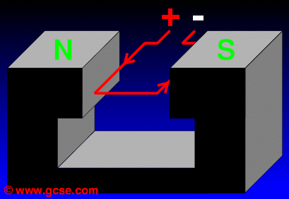
Look at the single coil of wire below. It is connected to a DC supply. Current flows, as shown by the red arrows.


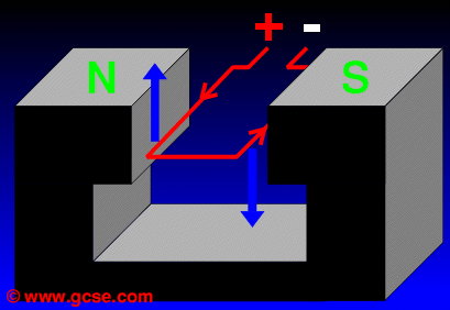
Use Fleming's Left Hand Rule to show that the left and right hand sides of the coil experience a force up and down.

Using the Left Hand Rule, you should work out that the wire experiences the following forces:


As a result, it will rotate clockwise. Let's see what will happen next.

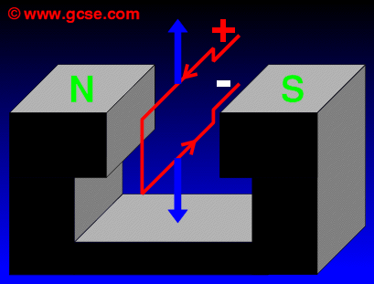
When the coil moves into the vertical postition (as long as the current is still flowing) the forces acting on the wires remain :


The forces act against each other: the coil will stop rotating! How then can a real motor keep going in the same direction? And how does it not twist its wires into a mess?

The Commutator

The answer is to use a commutator. This device prevents the wires from twisting. More importantly it actually allows the coil to keep rotating in one direction!


The one shown is a split-ring commutator. It has two halves, each connected to the power supply, completing the coil circuit. The coil is able to turn smoothly around it.

The commutator is made from two round pieces of copper, one on each side of the spindle. A piece of carbon (graphite) is lightly pushed against the copper
to conduct the electricity to the armature. The carbon brushes against the copper when the commutator spins.

In the vertical position there is no current as the coil has lost its connections to the commutator. Since the coil was already moving, it keeps turning. Think about riding a bike - stop pedalling and you don't stop moving for quite some time.

As the motor rotates, first one piece of copper, then the next connects with the brush every half turn. The wire on the left side of the armature always has current flowing in the same direction, and so the armature will keep turning in the same direction.


The pieces of copper are held apart in the centre and do not touch each other.
They look like a ring of copper which is split down the middle. This is why it is called a split - ring commutator.

Summary points: split-ring commutators reverse the direction of the current in the coil each half turn. This allows the motor coil to rotate continuously in one direction.

To increase the turning effect of the coil in the motor:

1.Insert a soft Iron core or cylinder into coil - to concentrate the magnetic field lines.

2. Increase the number of turns in the coil.

3. Increase the current in the coil.

Saturday, January 1, 2011

Electromagnetism

Magnetic Effect of a current


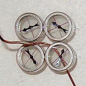
Th­e basic idea behind an electromagnet is extremely simple:Pass an electrical current through a wire and something amazing happens: a magnetic field is produced! You can show this by passing current through an insulated wire near a compass, although iron filings will also do.

Turning the current on and off will cause the compasses to deflect. Shown below are four compasses near a wire that comes towards the camera.


Magnetic Field around a straight wire


The shape of the magnetic field around a current-carrying conductor is rather curious: it is circular. The strongest deflection of compasses happens nearest to the wire.

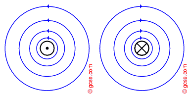
We can draw the field as a series of concentric circles around the wire as shown below. Notice that the circles are closer together nearer the wire: this indicates a stronger field.


Rather than awkwardly draw the field in some sort of 3D image, we normally draw them as if seeing the wire from above or below, as shown here:


The animation clearly shows that reversing the direction of the current reverses the direction of the magnetic field.

The magnetic field of a long, straight current-carrying wire is stronger:
(the field becomes stronger so we would draw more lines closer together)

1.increase the size of the current

2.when a larger current flows through the wire


Field Directions

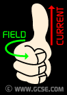
The direction of the field lines shows how a compass would line up if placed at that point. We can use the right hand grip rule to remember the relationship between current and field around a wire:


Grab the wire with your right fist (as shown), thumb pointing up: this is the direction of conventional current ( + to - ).

Your curled up fingers show the direction of the field.

An alternative way of remembering this is called the corkscrew rule: when screwing in a corkscrew to a bottle of wine, the point indicates the direction of the current, the the turning the field direction.

N.B. This does not, of course, work with left-handed corkscrews!


Magnetic field pattern around a flat coil and solenoid

When an electric current flows in a wire it creates a magnetic field around the wire.
By winding the wire into a coil we can strengthen the magnetic field. Electromagnets are made from coils like this, Making an electromagnet stronger.


A strong field can be made by coiling the wire around a piece of soft iron.
This electromagnet is sometimes called a solenoid. The shape of the magnetic field is the same as a bar magnet.


We can make an electromagnet stronger by doing these things:

* wrapping the coil around an iron core

* adding more turns to the coil

* increasing the current flowing through the coil.


Force on Current-carrying conductors


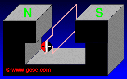
Place a current-carrying conductor in an external magnetic field (perhaps between two bar magnets), and the fields will push against each other. This force is incredibly important: it is the basis for all electric motors!


Normally the external field is fixed in place, so the force is only seen to act on the wire: moving it up or down. However, remember that forces come in pairs - the permanent magnets will experience the force too.


In the image above, the wire is at 90° to the direction of the magnetic field (which is between the poles of a horseshoe magnet).

Current is flowing to the left; the magnetic field diagonally towards us. This results in an upwards force on the wire.


If we reverse the direction of the current, the magnetic field around the wire reverses (surprise!). This reverses the force, so the wire deflects down:


A rather neat result of this effect is that if we pass alternating current (ac) through the wire, the direction of the force will continuously change. In the UK, ac is at a frequency of 50 Hz, so the wire can be seen vibrating up and down. This effect is used in speakers!

Fleming's Left Hand Rule


We have three directions to worry about: current, field and force. At GCSE we make sure the wire is held at 90° to the direction of the field. This makes life easier: the force is either up or down.

Current: dc - this is always from + to -
Field: direction is always from N to S.
Force: depends on how the other two align.

The left hand rule can be used to show how these three are related in a motor.

Sunday, December 26, 2010

Magnetic Field


A magnetic field is a region in which a magnetic object, placed within the influence of the field, experiences a magnetic force.


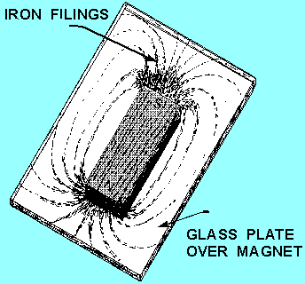
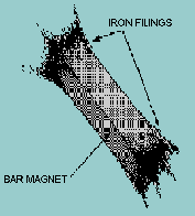
A pattern of this directional force can be obtained by performing an experiment with iron filings. A piece of glass is placed over a bar magnet and the iron filings are then sprinkled on the surface of the glass. The magnetizing force of the magnet will be felt through the glass and each iron filing becomes a temporary magnet.

If the glass is now tapped gently, the iron particles will align themselves with the magnetic field surrounding the magnet just as the compass needle did previously. The filings form a definite pattern known as the magnetic field pattern, which is a visible representation of the forces comprising the magnetic field. The magnetic field is very strong at the poles and weakens as the distance from the poles increases. It is also apparent that the magnetic field extends from one pole to the other, constituting a loop about the magnet.


Magnetic field lines between two magnets

Attraction

When two magnets or magnetic objects are close to each other, there is a force that attracts the poles together.


Magnets also strongly attract ferromagnetic materials such as iron, nickel and cobalt.

Repulsion

When two magnetic objects have like poles facing each other, the magnetic force pushes them apart.


Magnets can also weakly repel diamagnetic materials.


Temporary and Permanent magnets

• Permanent magnets — are able to retain their magnetism for long periods. They can be found around us as fridge magnets, bar magnets or button magnets used in games, or lodestones (natural magnets).

• Temporary magnets — are sometimes called induced magnets. They refer to magnetic materials that have been placed within a strong magnetic field and become magnets. These magnets lose their magnetism once they are removed from the magnetic field. Temporary magnets can be found in telephones, electric motors, and cranes at refuse dumps.

• Materials that are more easily magnetised tend to lose their magnetism more quickly. They are referred to as ‘soft’ magnetic materials. Examples include iron and alloys like MumetalTM (a nickel–iron alloy). ‘Hard’ magnetic materials, on the other hand, are much less easily magnetised, but they retain their magnetism for a longer time, e.g. steel.

• The Earth behaves like a giant magnet. Just like any magnet, it has two magnetic poles — North and South. These poles are not the same as the geographic North and South Poles that we see on world maps. The north-pole of a freely suspended bar magnet, such as that in a compass, points to the Earth’s magnetic North, which is near to its geographic North.

Saturday, December 25, 2010

Magnetisation and Demagnetisation

Theory of Magnetism and Magnetic Domains

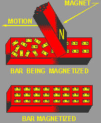
A popular theory of magnetism considers the molecular alignment of the material. This is known as Weber's theory. This theory assumes that all magnetic substances are composed of tiny molecular magnets.


Any unmagnetized material has the magnetic forces of its molecular magnets neutralized by adjacent molecular magnets, thereby eliminating any magnetic effect. A magnetized material will have most of its molecular magnets lined up so that the north pole of each molecule points in one direction, and the south pole faces the opposite direction. A material with its molecules thus aligned will then have one effective north pole, and one effective south pole.

An illustration of Weber's Theory is shown in figure 1-11, where a steel bar is magnetized by stroking. When a steel bar is stroked several times in the same direction by a magnet, the magnetic force from the north pole of the magnet causes the molecules to align themselves.

Ways of Making magnets

1. ‘Stroke’ method

A piece of magnetic material can be turned into a magnet if it is stroked by a magnet. As the magnet moves along the magnetic material, it causes the magnetic dipoles in the magnetic material to become aligned in one direction and give rise to a magnetic field.

2. Electrical method using a direct current

When a large direct current is passed through the solenoid, the unmagnetised steel bar will become magnetized after a while. This is because when an electric current flows through the solenoid, it produces a strong magnetic field which magnetizes the steel bar.

The poles of the magnet can be determind by a simple method known as Right-hand grip rule.


Ways of demagnetizing magnets

1. Heating

Heating a piece of magnetized metal in a flame will cause demagnetization by destroying the long-range order of molecules within the magnet. By heating a magnet, each molecule is infused with energy. This forces it to move, pushing each molecule out of order within the magnet and leaving the piece of metal with very little or no magnetization.

2. Hammering

When a magnet is hammered or dropped, the vibrations caused by the impact on the magnet randomize the magnetic molecules within the magnet, forcing them out of order and destroying the long-range order of the unit magnet.

3. Alternating Current (AC) Field

Using an AC current produces a magnetic field which can be moved and reduced to demagnetize materials. The field created by the AC current drags the magnetic molecules of the magnet in different directions. When the AC current is altered or reduced, the molecules within the magnet do not all return to previous positions, causing randomization of the molecules and reducing the force of the magnet.

Friday, December 24, 2010

Magnetism

Magnets and magnetic

Magnetism is a property of materials that respond at an atomic or subatomic level to an applied magnetic field. Some are attracted to a magnetic field (paramagnetism); others are repulsed by a magnetic field (diamagnetism); others have a much more complex relationship with an applied magnetic field. Substances that are negligibly affected by magnetic fields are known as non-magnetic substances. They include copper, aluminium, gases, and plastic.

Magnets attract (never repel) the , ferromagnets, "magnetic metals".
Ferromagnetic materials have the highest magnetic susceptibilities.Examples of ferromagnetic materials are Iron, Nickel, Cobalt, hematite, magnetite and ionized gases (such as the material stars are made of). Magnets also attract or repel other permanent magnets,depending on which way they are facing each other. Permanent magnets usually have some iron in them.

There is a kind of dark-gray brittle ceramic called "ferrite" (pronounced like
"fair-right"), which has iron, oxygen, and some other metals with oxygen.
Ferrite can be magnetic too, because of the iron in it.


Properties of magnets

1.Magnetic Poles


The magnetic force surrounding a magnet is not uniform. There exists a great concentration of force at each end of the magnet and a very weak force at the center.

Proof of this fact can be obtained by dipping a magnet into iron filings (fig. 1-8). It is found that many filings will cling to the ends of the magnet while very few adhere to the center.

The two ends, which are the regions of concentrated lines of force, are called the POLES of the magnet. Magnets have two magnetic poles and both poles have equal magnetic strength. The poles are where the magnetic effects are the strongest.

2.North and South Poles


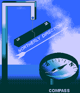
If a bar magnet is suspended freely on a string, it will align itself in a north and south direction. When this experiment is repeated, it is found that the same pole of the magnet will always swing toward the north magnetic pole of the earth. Therefore, it is called the north-seeking pole or simply the NORTH POLE. The other pole of the magnet is the south-seeking pole or the SOUTH POLE.

A practical use of the directional characteristic of the magnet is the compass, a device in which a freely rotating magnetized needle indicator points toward the North Pole.

3.Laws of magnetic poles

The realization that the poles of a suspended magnet always move to a definite position gives an indication that the opposite poles of a magnet have opposite magnetic polarity.The law previously stated regarding the attraction and repulsion of charged bodies may also be applied to magnetism if the pole is considered as a charge.

The north pole of a magnet will always be attracted to the south pole of another magnet and will show a repulsion to a north pole. The law of magnetism is:

Like poles repel, unlike poles attract.


How is magnet identified?

If an object attracts another object, it cannot be concluded to be a magnet as it may either be a magnetic material (not a magnet) that is attracted by the suspended magnet or a magnet itself with the opposite pole on the approaching end. To be certain, we would have to test the other end with the N pole of the suspended magnet to see if repulsion occurs.

Saturday, December 18, 2010

Dangers of Electricity

Electric Faults

Electric Faults in appliances or circuits can cause fires and electric shocks.
This can be caused due to three reasons: Damaged insulation, overheating of cables and damp conditions.


A lot of mains powered appliances need three wires to work safely. Only two of the wires are used when the appliance works properly. These are the live (brown) and the neutral (blue) wires. The live wire carries current to the appliance at a high voltage. The neutral wire completes the circuit and carries current away from the appliance. The third wire, called the earth wire (green/yellow) is a safety wire and connects the metal case of the appliance to the earth. This stops a fault making the case of the appliance live.


If a fault occurs where the live wire connects to the case, the earth wire allows a large current to flow through the live and earth wires. This overheats the fuse which melts and breaks the circuit.

Appliances such as hairdryers are said to be 'double insulated' and there's no need for an earth wire because the case is made of a non conducting plastic. If a faulty live wire touches the inside of the plastic case there's little risk as the case is an insulator.

Damaged Insulation


Insulation means putting something which does not conduct electricity (an insulator)
between a live conductor and yourself. The wires which we use to conduct electricity
are made of a high purity copper metal, which is an excellent conductor.

The insulator which covers the wires is a polymer called PVC (often just called "plastic"). It is an excellent insulator, flexible enough to bend around corners and cheap to make. Older wires had a rubber material as their insulation but the rubber becomes damaged due to wear and tear as it got older and so it has been replaced in houses by new PVC covered cable. If not replaced, this might cause the electrical insulation to break and crack.

Insulation can become unsafe if it is damaged or if it is wet because impure water will conduct electricity.The exposed live wire can cause severe electric shock to the user if it is touched. This can lead to serious injury or even death.


Overheating of cables


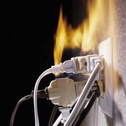
Plugging too many power cables into a socket can result in the socket being overloaded, overheating, and a fire starting as an unusually large current flows through the conducting wires.

Each wire in a power has a specific resistance depending on the specific thickness of the wires. The combined higher resistance of all wires will produce a more thermal heat that will damage the insulation and may cause a fire.

Solution: Never plug too many cables into a socket. Always make sure there are fire extinguishers nearby. Don’t use thin cable to carry large current.


Damp Conditions

Water or damp conditions allow current to flow outside the wires – keep electrics dry. It allows a conducting path for a large current to flow. A person could be electrocuted if the wires were exposed or had damaged insulation.

Other hazards include turning a switch on with wet hands.


Safe use of Electricity at home

Mains electricity is safe to use if we avoid touching a Live conductor,
and the current is kept down to a safe level.

Safety measures include :

Insulation

Double Insulation

Earthing

Fuses

Circuit Breakers


Circuit Breakers


The circuit breaker acts as a safety device in the same way as a fuse.
It disconnects the supply if too large a current flows.

When the live wire carries the usual operating current the electromagnet is not strong enough to separate the contacts. If something goes wrong with the appliance and a large current flows the electromagnet will pull hard enough to separate the contacts and break the circuit. The spring then keeps the contacts apart.

After the fault is repaired, the contacts can then be pushed back together
by pressing a button on the outside of the circuit breaker box.


Residual Current Circuit Breaker - RCCB or Earth Leakage Circuit Breaker - ELCB

This type of circuit breaker works by comparing
the current going in to an appliance with the current coming out.


When an appliance is working correctly
all of the current entering the appliance through the live wire
is returned to the power supply through the neutral wire.
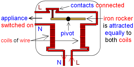
In the picture below the strength of the magnetic field
is the same in both coils because they both have the same current.


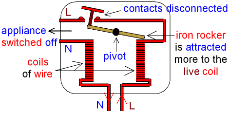
If something goes wrong with the appliance some of the electric current will flow through the earth wire. The amount of current flowing through the neutral wire decreases and now there is a difference between the current entering the appliance through the live wire and the current returned to the power supply through the neutral wire. This difference is called the residual current.

The coil connected to the neutral wire now has a weaker magnetic field than the coil connected to the live wire. The iron rocker turns about the pivot and the contacts are disconnected which switches off the appliance and makes it safe.
See the picture below.


Fuse


The fuse has a thin piece of wire inside it, which is the weakest link in a circuit.

A fuse is a safety device which switches off an appliance if too large a current flows through the Live wire. The fuse is connected between the Live pin and the Live wire of a plug.

The fuse has a rating printed on the outside in amps. If the current going through the fuse rises above its rated value, then the fuse "blows" (it melts) which turns off the appliance.This is so that the appliance will not become charged after the fuse has melted due to an overflow of current.

For example, if the fuse says 5 amps, then a current greater than 5 amps will blow the fuse.

Fuses are given different colours for different ratings.This is called colour coding.

A 2 amp fuse is blue,
3 amp is red,
5 amp is black (or very dark blue),
13 amp is brown.

A fuse has its own circuit symbol.

Most plugs come with a 13 amp fuse but a smaller fuse is needed for many appliances. This is how to do it:
1 . Look at the power rating (wattage) printed on the appliance.
2 . Divide the power (in watts) by 240 (house voltage).
3 . Before you change a fuse, always switch off the mains power supply.

The result is the current (amps) needed by the appliance. (Amps = watts ÷ volts)

Then choose a fuse with a slightly higher current rating.

For example, if your toaster says 1000 watts, the current it uses is: 1000 W ÷ 240 V = 4.2 A
So you would use a 5 A fuse.


Earthing

If the outer casing (the outside bit) of an appliance is a conductor (made of metal), then it can be made safe by Earthing. The Earth wire usually carries no electricity, it is connected to the metal case on the inside of the appliance.


If something goes wrong inside the appliance and the Live wire touches the metal case, then the Earth wire acts like a Neutral wire and completes the circuit for the electricity.

A very large current suddenly flows because the metal case has little resistance.
This large current blows the fuse in the plug and disconnects the appliance from the power supply.


Double Insulation.

Some appliances are double insulated. These appliances only need Live and Neutral wires, they do not need an Earth wire.

An appliance which is double insulated has the whole of the inside contained in plastic, underneath an outer casing. If anything goes wrong with the appliance,
no Live conductor can touch the outer casing because of the insulating plastic.


Appliances which are double insulated include electric drills and hairdryers.
The symbol for double insulation is shown below.


You will see this symbol printed on the appliance which is double insulated.