
Circuit symbol:

Diodes are kinds of device that allow current flow only in one direction in circuits. (The arrow of the circuit symbol shows the direction in which the current can flow.) Thus, only half of the cycles of alternating current can pass from the diodes. You can easily convert alternating current into the direct current with this device. Diodes are the electrical version of a valve and early diodes were actually called valves.
Following circuit shows the usage of diodes.
In the given circuit, D1 let current flow however, D2 does not let current flow.

Forward Voltage Drop
Electricity uses up a little energy pushing its way through the diode, rather like a person pushing through a door with a spring. This means that there is a small voltage across a conducting diode, it is called the forward voltage drop and is about 0.7V for all normal diodes which are made from silicon. The forward voltage drop of a diode is almost constant whatever the current passing through the diode so they have a very steep characteristic (current-voltage graph).
Reverse Voltage
When a reverse voltage is applied a perfect diode does not conduct, but all real diodes leak a very tiny current of a few µA or less. This can be ignored in most circuits because it will be very much smaller than the current flowing in the forward direction. However, all diodes have a maximum reverse voltage (usually 50V or more) and if this is exceeded the diode will fail and pass a large current in the reverse direction, this is called breakdown.
Ordinary diodes can be split into two types: Signal diodes which pass small currents of 100mA or less and Rectifier diodes which can pass large currents. In addition there are LEDs and Zener diodes
Rectifier diodes (large current)
Rectifier diodes are used in power supplies to convert alternating current (AC) to direct current (DC), a process called rectification. They are also used elsewhere in circuits where a large current must pass through the diode.
All rectifier diodes are made from silicon and therefore have a forward voltage drop of 0.7V. The table shows maximum current and maximum reverse voltage for some popular rectifier diodes. The 1N4001 is suitable for most low voltage circuits with a current of less than 1A.
Zener diodes

Circuit symbol:

Zener diodes are used to maintain a fixed voltage. They are designed to 'breakdown' in a reliable and non-destructive way so that they can be used in reverse to maintain a fixed voltage across their terminals. The diagram shows how they are connected, with a resistor in series to limit the current.
Zener diodes can be distinguished from ordinary diodes by their code and breakdown voltage which are printed on them. Zener diode codes begin BZX... or BZY... Their breakdown voltage is printed with V in place of a decimal point, so 4V7 means 4.7V for example.
Zener diodes are rated by their breakdown voltage and maximum power:
- The minimum voltage available is 2.4V.
- Power ratings of 400mW and 1.3W are common.

Bridge rectifiers
There are several ways of connecting diodes to make a rectifier to convert AC to DC. The bridge rectifier is one of them and it is available in special packages containing the four diodes required. Bridge rectifiers are rated by their maximum current and maximum reverse voltage. They have four leads or terminals: the two DC outputs are labelled + and -, the two AC inputs are labelled ~.
The diagram shows the operation of a bridge rectifier as it converts AC to DC. Notice how alternate pairs of diodes conduct.

Cathode Ray Oscilloscope
The cathode-ray oscilloscope (CRO) is a common laboratory instrument that provides accurate time and aplitude measurements of voltage signals over a wide range of frequencies. Its reliability, stability, and ease of operation make it suitable as a general purpose laboratory instrument. The heart of the CRO is a cathode-ray tube shown schematically in Fig. 1.

The cathode ray is a beam of electrons which are emitted by the heated cathode (negative electrode) and accelerated toward the fluorescent screen. The assembly of the cathode, intensity grid, focus grid, and accelerating anode (positive electrode) is called an electron gun. Its purpose is to generate the electron beam and control its intensity and focus. Between the electron gun and the fluorescent screen are two pair of metal plates - one oriented to provide horizontal deflection of the beam and one pair oriented ot give vertical deflection to the beam. These plates are thus referred to as the horizontal and vertical deflection plates. The combination of these two deflections allows the beam to reach any portion of the fluorescent screen. Wherever the electron beam hits the screen, the phosphor is excited and light is emitted from that point. This coversion of electron energy into light allows us to write with points or lines of light on an otherwise darkened screen.
In the most common use of the oscilloscope the signal to be studied is first amplified and then applied to the vertical (deflection) plates to deflect the beam vertically and at the same time a voltage that increases linearly with time is applied to the horizontal (deflection) plates thus causing the beam to be deflected horizontally at a uniform (constant> rate. The signal applied to the verical plates is thus displayed on the screen as a function of time. The horizontal axis serves as a uniform time scale.
The linear deflection or sweep of the beam horizontally is accomplished by use of a sweep generator that is incorporated in the oscilloscope circuitry.
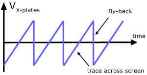
The voltage output of such a generator is that of a sawtooth wave as shown in Fig. 2. Application of one cycle of this voltage difference, which increases linearly with time, to the horizontal plates causes the beam to be deflected linearly with time across the tube face. When the voltage suddenly falls to zero, as at points (a) (b) (c), etc...., the end of each sweep - the beam flies back to its initial position. The horizontal deflection of the beam is repeated periodically, the frequency of this periodicity is adjustable by external controls.

CRO Operation:
A simplified block diagram of a typical oscilloscope is shown in Fig. 3. In general, the instrument is operated in the following manner. The signal to be displayed is amplified by the vertical amplifier and applied to the verical deflection plates of the CRT. A portion of the signal in the vertical amplifier is applied to the sweep trigger as a triggering signal. The sweep trigger then generates a pulse coincident with a selected point in the cycle of the triggering signal. This pulse turns on the sweep generator, initiating the sawtooth wave form.
The sawtooth wave is amplified by the horizontal amplifier and applied to the horizontal deflection plates. Usually, additional provisions signal are made for appliying an external triggering signal or utilizing the 60 Hz line for triggering. Also the sweep generator may be bypassed and an external signal applied directly to the horizontal amplifier.
CRO Controls
The controls available on most oscilloscopes provide a wide range of operating conditions and thus make the instrument especially versatile. Since many of these controls are common to most oscilloscopes a brief description of them follows.
Measurements of Voltage:
Consider the circuit in Fig. 4(a). The signal generator is used to produce a 1000 hertz sine wave. The AC voltmeter and the leads to the verticle input of the oscilloscope are connected across the generator's output. By adjusting the Horizontal Sweep time/cm and trigger, a steady trace of the sine wave may be displayed on the screen. The trace represents a plot of voltage vs. time, where the vertical deflection of the trace about the line of symmetry CD is proportional to the magnitude of the voltage at any instant of time.

To determine the size of the voltage signal appearing at the output of terminals of the signal generator, an AC (Alternating Current) voltmeter is connected in parallel across these terminals (Fig. 4a). The AC voltmeter is designed to read the dc "effective value" of the voltage. This effective value is also known as the "Root Mean Square value" (RMS) value of the voltage.
The peak or maximum voltage seen on the scope face (Fig. 4b) is Vm volts and is represented by the distance from the symmetry line CD to the maximum deflection. The relationship between the magnitude of the peak voltage displayed on the scope and the effective or RMS voltage (VRMS) read on the AC voltmeter is
VRMS = 0.707 Vm (for a sine or cosine wave).
Thus,
Agreement is expected between the voltage reading of the multimeter and that of the oscilloscope. For a symmetric wave (sine or cosine) the value of Vm may be taken as 1/2 the peak to peak signal Vpp
The variable sensitivity control a signal may be used to adjust the display to fill a concenient range of the scope face. In this position, the trace is no longer calibrated so that you can not just read the size of the signal by counting the number of divisions and multiplying by the scale factor. However, you can figure out what the new calibration is an use it as long as the variable control remains unchanged.
For more information on CRO and measurement of voltage, Visit:
Schoolphysics.co.uk
vsagar.com
There are three main types of mini dehumidifier with each having its strength and weakness and using Liquid Control Distributor information one will be able to make a valid decision when purchasing the mini dehumidifier. The three mini dehumidifiers are the heated rod dehumidifier, the thermoelectric dehumidifier, and the rechargeable dehumidifier.
ReplyDelete