Sunday, December 26, 2010

Magnetic Field


A magnetic field is a region in which a magnetic object, placed within the influence of the field, experiences a magnetic force.


A pattern of this directional force can be obtained by performing an experiment with iron filings. A piece of glass is placed over a bar magnet and the iron filings are then sprinkled on the surface of the glass. The magnetizing force of the magnet will be felt through the glass and each iron filing becomes a temporary magnet.

If the glass is now tapped gently, the iron particles will align themselves with the magnetic field surrounding the magnet just as the compass needle did previously. The filings form a definite pattern known as the magnetic field pattern, which is a visible representation of the forces comprising the magnetic field. The magnetic field is very strong at the poles and weakens as the distance from the poles increases. It is also apparent that the magnetic field extends from one pole to the other, constituting a loop about the magnet.


Magnetic field lines between two magnets

Attraction

When two magnets or magnetic objects are close to each other, there is a force that attracts the poles together.


Magnets also strongly attract ferromagnetic materials such as iron, nickel and cobalt.

Repulsion

When two magnetic objects have like poles facing each other, the magnetic force pushes them apart.


Magnets can also weakly repel diamagnetic materials.


Temporary and Permanent magnets

• Permanent magnets — are able to retain their magnetism for long periods. They can be found around us as fridge magnets, bar magnets or button magnets used in games, or lodestones (natural magnets).

• Temporary magnets — are sometimes called induced magnets. They refer to magnetic materials that have been placed within a strong magnetic field and become magnets. These magnets lose their magnetism once they are removed from the magnetic field. Temporary magnets can be found in telephones, electric motors, and cranes at refuse dumps.

• Materials that are more easily magnetised tend to lose their magnetism more quickly. They are referred to as ‘soft’ magnetic materials. Examples include iron and alloys like MumetalTM (a nickel–iron alloy). ‘Hard’ magnetic materials, on the other hand, are much less easily magnetised, but they retain their magnetism for a longer time, e.g. steel.

• The Earth behaves like a giant magnet. Just like any magnet, it has two magnetic poles — North and South. These poles are not the same as the geographic North and South Poles that we see on world maps. The north-pole of a freely suspended bar magnet, such as that in a compass, points to the Earth’s magnetic North, which is near to its geographic North.

Saturday, December 25, 2010

Magnetisation and Demagnetisation

Theory of Magnetism and Magnetic Domains

A popular theory of magnetism considers the molecular alignment of the material. This is known as Weber's theory. This theory assumes that all magnetic substances are composed of tiny molecular magnets.


Any unmagnetized material has the magnetic forces of its molecular magnets neutralized by adjacent molecular magnets, thereby eliminating any magnetic effect. A magnetized material will have most of its molecular magnets lined up so that the north pole of each molecule points in one direction, and the south pole faces the opposite direction. A material with its molecules thus aligned will then have one effective north pole, and one effective south pole.

An illustration of Weber's Theory is shown in figure 1-11, where a steel bar is magnetized by stroking. When a steel bar is stroked several times in the same direction by a magnet, the magnetic force from the north pole of the magnet causes the molecules to align themselves.

Ways of Making magnets

1. ‘Stroke’ method

A piece of magnetic material can be turned into a magnet if it is stroked by a magnet. As the magnet moves along the magnetic material, it causes the magnetic dipoles in the magnetic material to become aligned in one direction and give rise to a magnetic field.

2. Electrical method using a direct current

When a large direct current is passed through the solenoid, the unmagnetised steel bar will become magnetized after a while. This is because when an electric current flows through the solenoid, it produces a strong magnetic field which magnetizes the steel bar.

The poles of the magnet can be determind by a simple method known as Right-hand grip rule.


Ways of demagnetizing magnets

1. Heating

Heating a piece of magnetized metal in a flame will cause demagnetization by destroying the long-range order of molecules within the magnet. By heating a magnet, each molecule is infused with energy. This forces it to move, pushing each molecule out of order within the magnet and leaving the piece of metal with very little or no magnetization.

2. Hammering

When a magnet is hammered or dropped, the vibrations caused by the impact on the magnet randomize the magnetic molecules within the magnet, forcing them out of order and destroying the long-range order of the unit magnet.

3. Alternating Current (AC) Field

Using an AC current produces a magnetic field which can be moved and reduced to demagnetize materials. The field created by the AC current drags the magnetic molecules of the magnet in different directions. When the AC current is altered or reduced, the molecules within the magnet do not all return to previous positions, causing randomization of the molecules and reducing the force of the magnet.

Friday, December 24, 2010

Magnetism

Magnets and magnetic

Magnetism is a property of materials that respond at an atomic or subatomic level to an applied magnetic field. Some are attracted to a magnetic field (paramagnetism); others are repulsed by a magnetic field (diamagnetism); others have a much more complex relationship with an applied magnetic field. Substances that are negligibly affected by magnetic fields are known as non-magnetic substances. They include copper, aluminium, gases, and plastic.

Magnets attract (never repel) the , ferromagnets, "magnetic metals".
Ferromagnetic materials have the highest magnetic susceptibilities.Examples of ferromagnetic materials are Iron, Nickel, Cobalt, hematite, magnetite and ionized gases (such as the material stars are made of). Magnets also attract or repel other permanent magnets,depending on which way they are facing each other. Permanent magnets usually have some iron in them.

There is a kind of dark-gray brittle ceramic called "ferrite" (pronounced like
"fair-right"), which has iron, oxygen, and some other metals with oxygen.
Ferrite can be magnetic too, because of the iron in it.


Properties of magnets

1.Magnetic Poles


The magnetic force surrounding a magnet is not uniform. There exists a great concentration of force at each end of the magnet and a very weak force at the center.

Proof of this fact can be obtained by dipping a magnet into iron filings (fig. 1-8). It is found that many filings will cling to the ends of the magnet while very few adhere to the center.

The two ends, which are the regions of concentrated lines of force, are called the POLES of the magnet. Magnets have two magnetic poles and both poles have equal magnetic strength. The poles are where the magnetic effects are the strongest.

2.North and South Poles


If a bar magnet is suspended freely on a string, it will align itself in a north and south direction. When this experiment is repeated, it is found that the same pole of the magnet will always swing toward the north magnetic pole of the earth. Therefore, it is called the north-seeking pole or simply the NORTH POLE. The other pole of the magnet is the south-seeking pole or the SOUTH POLE.

A practical use of the directional characteristic of the magnet is the compass, a device in which a freely rotating magnetized needle indicator points toward the North Pole.

3.Laws of magnetic poles

The realization that the poles of a suspended magnet always move to a definite position gives an indication that the opposite poles of a magnet have opposite magnetic polarity.The law previously stated regarding the attraction and repulsion of charged bodies may also be applied to magnetism if the pole is considered as a charge.

The north pole of a magnet will always be attracted to the south pole of another magnet and will show a repulsion to a north pole. The law of magnetism is:

Like poles repel, unlike poles attract.


How is magnet identified?

If an object attracts another object, it cannot be concluded to be a magnet as it may either be a magnetic material (not a magnet) that is attracted by the suspended magnet or a magnet itself with the opposite pole on the approaching end. To be certain, we would have to test the other end with the N pole of the suspended magnet to see if repulsion occurs.

Saturday, December 18, 2010

Dangers of Electricity

Electric Faults

Electric Faults in appliances or circuits can cause fires and electric shocks.
This can be caused due to three reasons: Damaged insulation, overheating of cables and damp conditions.


A lot of mains powered appliances need three wires to work safely. Only two of the wires are used when the appliance works properly. These are the live (brown) and the neutral (blue) wires. The live wire carries current to the appliance at a high voltage. The neutral wire completes the circuit and carries current away from the appliance. The third wire, called the earth wire (green/yellow) is a safety wire and connects the metal case of the appliance to the earth. This stops a fault making the case of the appliance live.


If a fault occurs where the live wire connects to the case, the earth wire allows a large current to flow through the live and earth wires. This overheats the fuse which melts and breaks the circuit.

Appliances such as hairdryers are said to be 'double insulated' and there's no need for an earth wire because the case is made of a non conducting plastic. If a faulty live wire touches the inside of the plastic case there's little risk as the case is an insulator.

Damaged Insulation


Insulation means putting something which does not conduct electricity (an insulator)
between a live conductor and yourself. The wires which we use to conduct electricity
are made of a high purity copper metal, which is an excellent conductor.

The insulator which covers the wires is a polymer called PVC (often just called "plastic"). It is an excellent insulator, flexible enough to bend around corners and cheap to make. Older wires had a rubber material as their insulation but the rubber becomes damaged due to wear and tear as it got older and so it has been replaced in houses by new PVC covered cable. If not replaced, this might cause the electrical insulation to break and crack.

Insulation can become unsafe if it is damaged or if it is wet because impure water will conduct electricity.The exposed live wire can cause severe electric shock to the user if it is touched. This can lead to serious injury or even death.


Overheating of cables


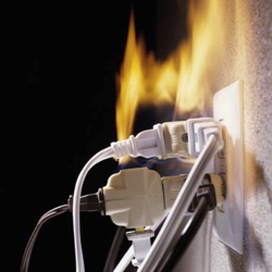
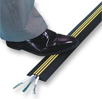
Plugging too many power cables into a socket can result in the socket being overloaded, overheating, and a fire starting as an unusually large current flows through the conducting wires.

Each wire in a power has a specific resistance depending on the specific thickness of the wires. The combined higher resistance of all wires will produce a more thermal heat that will damage the insulation and may cause a fire.

Solution: Never plug too many cables into a socket. Always make sure there are fire extinguishers nearby. Don’t use thin cable to carry large current.


Damp Conditions

Water or damp conditions allow current to flow outside the wires – keep electrics dry. It allows a conducting path for a large current to flow. A person could be electrocuted if the wires were exposed or had damaged insulation.

Other hazards include turning a switch on with wet hands.


Safe use of Electricity at home

Mains electricity is safe to use if we avoid touching a Live conductor,
and the current is kept down to a safe level.

Safety measures include :

Insulation

Double Insulation

Earthing

Fuses

Circuit Breakers


Circuit Breakers


The circuit breaker acts as a safety device in the same way as a fuse.
It disconnects the supply if too large a current flows.

When the live wire carries the usual operating current the electromagnet is not strong enough to separate the contacts. If something goes wrong with the appliance and a large current flows the electromagnet will pull hard enough to separate the contacts and break the circuit. The spring then keeps the contacts apart.

After the fault is repaired, the contacts can then be pushed back together
by pressing a button on the outside of the circuit breaker box.


Residual Current Circuit Breaker - RCCB or Earth Leakage Circuit Breaker - ELCB

This type of circuit breaker works by comparing
the current going in to an appliance with the current coming out.


When an appliance is working correctly
all of the current entering the appliance through the live wire
is returned to the power supply through the neutral wire.
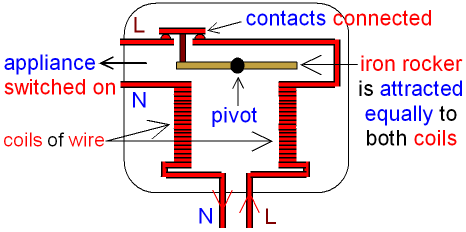
In the picture below the strength of the magnetic field
is the same in both coils because they both have the same current.


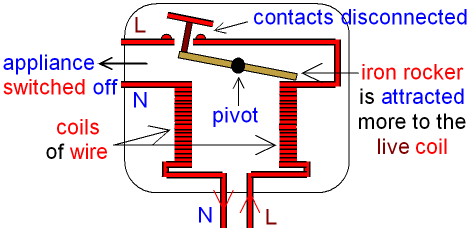
If something goes wrong with the appliance some of the electric current will flow through the earth wire. The amount of current flowing through the neutral wire decreases and now there is a difference between the current entering the appliance through the live wire and the current returned to the power supply through the neutral wire. This difference is called the residual current.

The coil connected to the neutral wire now has a weaker magnetic field than the coil connected to the live wire. The iron rocker turns about the pivot and the contacts are disconnected which switches off the appliance and makes it safe.
See the picture below.


Fuse


The fuse has a thin piece of wire inside it, which is the weakest link in a circuit.

A fuse is a safety device which switches off an appliance if too large a current flows through the Live wire. The fuse is connected between the Live pin and the Live wire of a plug.

The fuse has a rating printed on the outside in amps. If the current going through the fuse rises above its rated value, then the fuse "blows" (it melts) which turns off the appliance.This is so that the appliance will not become charged after the fuse has melted due to an overflow of current.

For example, if the fuse says 5 amps, then a current greater than 5 amps will blow the fuse.

Fuses are given different colours for different ratings.This is called colour coding.

A 2 amp fuse is blue,
3 amp is red,
5 amp is black (or very dark blue),
13 amp is brown.

A fuse has its own circuit symbol.

Most plugs come with a 13 amp fuse but a smaller fuse is needed for many appliances. This is how to do it:
1 . Look at the power rating (wattage) printed on the appliance.
2 . Divide the power (in watts) by 240 (house voltage).
3 . Before you change a fuse, always switch off the mains power supply.

The result is the current (amps) needed by the appliance. (Amps = watts ÷ volts)

Then choose a fuse with a slightly higher current rating.

For example, if your toaster says 1000 watts, the current it uses is: 1000 W ÷ 240 V = 4.2 A
So you would use a 5 A fuse.


Earthing

If the outer casing (the outside bit) of an appliance is a conductor (made of metal), then it can be made safe by Earthing. The Earth wire usually carries no electricity, it is connected to the metal case on the inside of the appliance.


If something goes wrong inside the appliance and the Live wire touches the metal case, then the Earth wire acts like a Neutral wire and completes the circuit for the electricity.

A very large current suddenly flows because the metal case has little resistance.
This large current blows the fuse in the plug and disconnects the appliance from the power supply.


Double Insulation.

Some appliances are double insulated. These appliances only need Live and Neutral wires, they do not need an Earth wire.

An appliance which is double insulated has the whole of the inside contained in plastic, underneath an outer casing. If anything goes wrong with the appliance,
no Live conductor can touch the outer casing because of the insulating plastic.


Appliances which are double insulated include electric drills and hairdryers.
The symbol for double insulation is shown below.


You will see this symbol printed on the appliance which is double insulated.

Friday, December 17, 2010

Practical Electricity

Measuring Electrical Energy

Electrical Power, P

P = W / t ---(1)

or

P = E / t ---(2)

where,

P - Power in Watts(W)
W - Work done in Joules(J)
E - Energy in Joules(J)
t - time in seconds(s)

V = W / Q ---(3)

where.

V - Potential Difference in Volts(V)
W - Work done in Joules(J)
Q - Charge in Coulombs(C)

From (3)

W = Q x V ---(4)

Substituting (4) into (1)

P = (Q x V) / t ---(5)

Substitute Q = I x t into (5)

P = V x I ---(6)

Substitute V = I x R into (6)

P = I x I x R ---(7)

Substitute I = V / R into (5)

P = (V x V) / R ---(8)

The S.I. unit for Power is Watts(W).

1 Kilowatt = 1000 W
1 megawatt = 1 000 000 W

Electrical Energy, E

From (2)

E = P x t ---(9)

Substitute (6),(7) and (8) into (9)

E = V x I x t = I x I x R x t = (V x V x t) / R

The S.I. unit of Energy is Joule(J).

1 Kilo joule = 1000 J
1 Mega joule = 1 000 000 J

Energy and the Cost

Kilowatt-hours (kWh)

The kilowatt-hour is the common unit used by energy companies to measure electricity. This is a unit of energy not power or time. It is the amount of energy if a 1kW appliance was left on for 1 hour.

The Cost

1kWh of electrical energy costs around 6p, though it may change depending on your supplier. So multiplying the number of Kilowatt-hours you use by the unit cost (approx 6p), give you the total cost of the electricity you use.

Know that:

  • an electricity bill will often refer to the electrical energy consumed in terms of units
  • One unit in this context is just a shorthand way of saying one kilowatt-hour --> 1 unit = 1kWh.
You should be able to use the formula: cost of electricity used = number of units used × cost of each unit

Saturday, December 11, 2010

Potential Divider and Transducers

Potential Divider

The "Potential Divider" is a line of resistors in series that are used to give different voltages in parts of an electronic circuit. The voltages can either be set to fixed values or be adjustable. As the name says, it divides the "potential" (voltage) into different amounts.


Fixed Potential Divider.

The Supply voltage is 9V
The two resistors in series have equal values and they divide the supply voltage into two equal parts allowing a voltage of 4.5V to be supplied to another part of the circuit.Three resistors of equal value would divide the supply voltage into three, allowing 3V, 6V and 9V to be used by the rest of the circuit.

Potential dividers are often placed directly after the supply source to allow different voltages to be feed directly to different parts of the circuit. In the Op-Amp comparator circuit below, the potential divider network of two 10K resistors give a fixed voltage on Pin 3 equal to half the supply voltage.


To find the values of resistors in a Potential Divider network to obtain a particular output value, use the following method.

Calculations

Knowing the values of the resistors, it is simple to calculate the Output Voltage using the following formula.


To find the values of resistors in a Potential Divider network to obtain a particular output value, use the following method.


Transducers


A transducer is an electric or electronic device that converts one type of energy to another. The conversion can be to/from electrical, electro-mechanical, electromagnetic, photonic, photovoltaic, or any other form of energy. While the term transducer commonly implies use as a sensor/detector, any device which converts energy can be considered a transducer.


Input and output Transducers


Input Transducers convert a quantity to an electrical signal (voltage) or to resistance (which can be converted to voltage). Input transducers are also called sensors.


LDR

Examples:

  • LDR converts brightness (of light) to resistance.
  • Thermistor converts temperature to resistance.
  • Microphone converts sound to voltage.
  • Variable resistor converts position (angle) to resistance.


Output Transducers convert an electrical signal to another quantity


Loudspeaker

Examples:

  • Lamp converts electricity to light.
  • LED converts electricity to light.
  • Loudspeaker converts electricity to sound.
  • Motor converts electricity to motion.
  • Heater converts electricity to heat.


Most input transducers (sensors) vary their resistance and this can be used directly in some circuits but it is usually converted to an electrical signal in the form of a voltage.

The voltage signal can be fed to other parts of the circuit, such as the input to an IC or a transistor switch.

The conversion of varying resistance to varying voltage is performed by a simple voltage divider.

Hence, the calculation of voltage is done through the
potential divider formula (for both input and output transducers).

D.C. Circuits

Series Circuits

A series circuits has only one path for electrons through which electric charge can flow.


Current in Series circuit

The amount of current is the same through any component in the circuit.This is because there is only one path for electrons to flow in a series circuit, and because free electrons flow through conductors like marbles in a tube, the rate of flow (marble speed) at any point in the circuit (tube) at any specific point in time must be equal.

Charge does NOT become used up by resistors such that there is less of it at one location compared to another.

Ibattery = I1 = I2 = I3 = ...

where I1, I2, and I3 are the current values at the individual resistor locations.

These current values are easily calculated if the battery voltage is known and the individual resistance values are known. Using the individual resistor values and the equation above, the equivalent resistance can be calculated. And using Ohm's law (V = I • R), the current in the battery and thus through every resistor can be determined by finding the ratio of the battery voltage and the equivalent resistance.

Ibattery = I1 = I2 = I3 = Vbattery / Req


Resistance in Series Current


The actual amount of current varies inversely with the amount of overall resistance. There is a clear relationship between the resistance of the individual resistors and the overall resistance of the collection of resistors. As far as the battery that is pumping the charge is concerned, the presence of two 6- resistors in series would be equivalent to having one 12- resistor in the circuit. The presence of three 6- resistors in series would be equivalent to having one 18- resistor in the circuit.


This is the concept of equivalent resistance. The equivalent resistance of a circuit is the amount of resistance that a single resistor would need in order to equal the overall affect of the collection of resistors that are present in the circuit. For series circuits, the mathematical formula for computing the equivalent resistance (Req) is

Req = R1 + R2 + R3 + ...

where R1, R2, and R3 are the resistance values of the individual resistors that are connected in series.


Electric Potential Difference and Voltage Drops

The electrochemical cell of a circuit supplies energy to the charge to move it through the cell and to establish an electric potential difference across the two ends of the external circuit. A 1.5-volt cell will establish an electric potential difference across the external circuit of 1.5 volts. This is to say that the electric potential at the positive terminal is 1.5 volts greater than at the negative terminal. As charge moves through the external circuit, it encounters a loss of 1.5 volts of electric potential. This loss in electric potential is referred to as a voltage drop. It occurs as the electrical energy of the charge is transformed to other forms of energy (thermal, light, mechanical, etc.) within the resistors or loads. If an electric circuit powered by a 1.5-volt cell is equipped with more than one resistor, then the cumulative loss of electric potential is 1.5 volts. There is a voltage drop for each resistor, but the sum of these voltage drops is 1.5 volts - the same as the voltage rating of the power supply.


This concept can be expressed mathematically by the following equation:


Vbattery = V1 + V2 + V3 + ...


Parallel Circuits


In a parallel arrangement, there is more than one path through which electric charge can flow.


Current in Parallel Circuits

he current divides to flow through each of the components in the parallel paths. The amount of current that flows through each of the components depends on the resistance of each component. A component with a lower resistance will allow more current to flow through.

The current outside the branches is the same as the sum of the current in the individual branches. It is still the same amount of current, only split up into more than one pathway.


In equation form, this principle can be written as

Itotal = I1 + I2 + I3 + ...

where Itotal is the total amount of current outside the branches (and in the battery) and I1, I2, and I3 represent the current in the individual branches of the circuit.


Resistance in Parallel Circuit


The actual amount of current always varies inversely with the amount of overall resistance. There is a clear relationship between the resistance of the individual resistors and the overall resistance of the collection of resistors.

To explore this relationship, let's begin with the simplest case of two resistors placed in parallel branches, each having the same resistance value of 4 . Since the circuit offers two equal pathways for charge flow, only one-half the charge will choose to pass through a given branch.

While each individual branch offers 4 of resistance to any charge that flows through it, only one-half of all the charge flowing through the circuit will encounter the 4 resistance of that individual branch. Thus, as far as the battery that is pumping the charge is concerned, the presence of two 4- resistors in parallel would be equivalent to having one 2- resistor in the circuit.


This is the concept of equivalent resistance. The equivalent resistance of a circuit is the amount of resistance that a single resistor would need in order to equal the overall effect of the collection of resistors that are present in the circuit. For parallel circuits, the mathematical formula for computing the equivalent resistance (Req) is

1 / Req = 1 / R1 + 1 / R2 + 1 / R3 + ...

where R1, R2, and R3 are the resistance values of the individual resistors that are connected in parallel. The examples above could be considered simple cases in which all the pathways offer the same amount of resistance to an individual charge that passes through it. The simple cases above were done without the use of the equation. Yet the equation fits both the simple cases where branch resistors have the same resistance values and the more difficult cases where branch resistors have different resistance values. For instance, consider the application of the equation to the one simple and one difficult case below.


Example : Three 12 resistors are placed in parallel


1/Req = 1/R1 + 1/R2 + 1/R3

1/Req = 1/(12 ) + 1/(12 ) + 1/(12 )

Using a calculator ...

1/Req = 0.25 -1

Req = 1 / (0.25 -1)

Req = 4.0

The total voltage drop in the external circuit is equal to the gain in voltage as a charge passes through the internal circuit. In a parallel circuit, a charge does not pass through every resistor; rather, it passes through a single resistor. Thus, the entire voltage drop across that resistor must match the battery voltage. It matters not whether the charge passes through resistor 1, resistor 2, or resistor 3, the voltage drop across the resistor that it chooses to pass through must equal the voltage of the battery. Put in equation form, this principle would be expressed as

Vbattery = V1 = V2 = V3 = ...

If three resistors are placed in parallel branches and powered by a 12-volt battery, then the voltage drop across each one of the three resistors is 12 volts. A charge flowing through the circuit would only encounter one of these three resistors and thus encounter a single voltage drop of 12 volts.


Summary


Series Circuits

  • The current is the same in every resistor; this current is equal to that in the battery.
  • The sum of the voltage drops across the individual resistors is equal to the voltage rating of the battery.
  • The overall resistance of the collection of resistors is equal to the sum of the individual resistance values,
Rtot = R1 + R2 + R3 + ...

Parallel Circuits

  • The voltage drop is the same across each parallel branch.
  • The sum of the current in each individual branch is equal to the current outside the branches.
  • The equivalent or overall resistance of the collection of resistors is given by the equation
    1/Req = 1/R1 + 1/R2 + 1/R3 ...

Sunday, December 5, 2010

Resistance

What is resistance?

The electrical resistance of an object is a measure of its opposition to the passage of an electric current.

It is a property of the material that restricts the movement of free electrons in the material.It determines the size of the electric current passing through the material.


Measuring Resistance


The resistance R of a component is defined as the ratio of the potential difference V across it to the current I flowing through it.


Where,

R - resistance,
I - current flowing through the circuit,
V - p.d. across component

The SI unit for resistance is Ohm ().


Measuring resistance

An instrument for measuring resistance is called an ohmmeter. Simple ohmmeters cannot measure low resistances accurately because the resistance of their measuring leads causes a voltage drop that interferes with the measurement, so more accurate devices use four-terminal sensing.


Ohm's Law

The relationship between voltage*, resistance* and current* is expressed in Ohm's Law which is named after the physicist who discovered it.

Ohm's law states that the current through a conductor between two points is directly proportional to the potential difference or voltage across the two points, and inversely proportional to the resistance between them.

Ohm's Law most simply translates to the equation,

V = IR,

Voltage = Current × Resistance

or


where,

I - current through the resistance in amperes,A.
V - potential difference measured across the resistance in volts,V.
R - resistance of the conductor in units of ohms,Ω.

More specifically, Ohm's law states that the R in this relation is constant, independent of the current

If the resistance of a component is constant (stays the same) for different values of V and I, then a plot (graph) of V against I will be a straight line.
The gradient (slope) of the line shows how big the resistance is.


This is all, however, when all physical conditions are constant (e.g. at constant temperature).

Worked Example

Bicycles with battery operated lights often have different size bulbs for the front and rear lights. The filament in the front lamp has a resistance of 3 ohms. It takes a current of 0.6A. What voltage does it work at?

1. 0.2V
2. 1.5V
3. 1.8V
4. 5V

Answer

The answer is 1.8V. If you didn't get the correct answer, have another look at the formula before you try again.


Series circuits

When components are connected in series, their total resistance is the sum of their individual resistances. For example, if a 2Ω resistor, a 1Ω resistor and a 3Ω resistor are connected side by side, their total resistance is 2 + 1 + 3 = 6Ω.


Sum of resistance is 6 ohms

If you increase the number of lamps in a series circuit, the total resistance will increase and less current will flow.


Variable resistors

The resistance in a circuit can also be changed using variable resistors. For example, these components may be used in dimmer switches, or to control the volume of a CD player.


The filament lamp

You should be able to recognise the graph of current against voltage for a filament lamp.


Background

a circle with a diagonal cross through the middle.


Filament lamp symbol

The filament lamp is a common type of light bulb. It contains a thin coil of wire called the filament. This heats up when an electric current passes through it and produces light as a result.

Ohm's Law revisited

graph showing current on the y axis and voltage on the x axis. A line is drawn through the centre of the graph at 45 degrees.


Relationship between current and voltage when a resistor follows Ohm's Law

Remember that the current flowing through a resistor at a constant temperature is directly proportional to the voltage across the resistor. The graph shows what happens to the current and voltage when a resistor follows Ohm's Law.


The filament lamp

The filament lamp does not follow Ohm's Law. The resistance of a filament lamp increases as the temperature of its filament increases. As a result, the current flowing through a filament lamp is not directly proportional to the voltage across it. This is the graph of current against voltage for a filament lamp.


Relationship between current and voltage for a filament lamp

The thermistor

Thermistors are used as temperature sensors, for example, in fire alarms. Their resistance decreases as the temperature increases:


Thermistor symbol

* At low temperatures, the resistance of a thermistor is high, and little current can flow through them.
* At high temperatures, the resistance of a thermistor is low, and more current can flow through them.