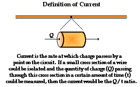
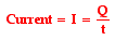
The electrical resistance of an object is a measure of its opposition to the passage of an electric current.
It is a property of the material that restricts the movement of free electrons in the material.It determines the size of the electric current passing through the material.
Measuring Resistance

The resistance R of a component is defined as the ratio of the potential difference V across it to the current I flowing through it.

Where,
R - resistance,
I - current flowing through the circuit,
V - p.d. across component
The SI unit for resistance is Ohm (
 ).
).Measuring resistance
An instrument for measuring resistance is called an ohmmeter. Simple ohmmeters cannot measure low resistances accurately because the resistance of their measuring leads causes a voltage drop that interferes with the measurement, so more accurate devices use four-terminal sensing.
Ohm's Law
The relationship between voltage*, resistance* and current* is expressed in Ohm's Law which is named after the physicist who discovered it.
Ohm's law states that the current through a conductor between two points is directly proportional to the potential difference or voltage across the two points, and inversely proportional to the resistance between them.
Ohm's Law most simply translates to the equation,
V = IR,
Voltage = Current × Resistance
or

where,
I - current through the resistance in amperes,A.
V - potential difference measured across the resistance in volts,V.
R - resistance of the conductor in units of ohms,Ω.
More specifically, Ohm's law states that the R in this relation is constant, independent of the current
If the resistance of a component is constant (stays the same) for different values of V and I, then a plot (graph) of V against I will be a straight line.
The gradient (slope) of the line shows how big the resistance is.

This is all, however, when all physical conditions are constant (e.g. at constant temperature).
Worked Example
Bicycles with battery operated lights often have different size bulbs for the front and rear lights. The filament in the front lamp has a resistance of 3 ohms. It takes a current of 0.6A. What voltage does it work at?
1. 0.2V
2. 1.5V
3. 1.8V
4. 5V
Answer
The answer is 1.8V. If you didn't get the correct answer, have another look at the formula before you try again.
Series circuits
When components are connected in series, their total resistance is the sum of their individual resistances. For example, if a 2Ω resistor, a 1Ω resistor and a 3Ω resistor are connected side by side, their total resistance is 2 + 1 + 3 = 6Ω.

Sum of resistance is 6 ohms
If you increase the number of lamps in a series circuit, the total resistance will increase and less current will flow.
Variable resistors
The resistance in a circuit can also be changed using variable resistors. For example, these components may be used in dimmer switches, or to control the volume of a CD player.
The filament lamp
You should be able to recognise the graph of current against voltage for a filament lamp.
Background
a circle with a diagonal cross through the middle.

Filament lamp symbol
The filament lamp is a common type of light bulb. It contains a thin coil of wire called the filament. This heats up when an electric current passes through it and produces light as a result.
Ohm's Law revisited
graph showing current on the y axis and voltage on the x axis. A line is drawn through the centre of the graph at 45 degrees.

Relationship between current and voltage when a resistor follows Ohm's Law
Remember that the current flowing through a resistor at a constant temperature is directly proportional to the voltage across the resistor. The graph shows what happens to the current and voltage when a resistor follows Ohm's Law.
The filament lamp
The filament lamp does not follow Ohm's Law. The resistance of a filament lamp increases as the temperature of its filament increases. As a result, the current flowing through a filament lamp is not directly proportional to the voltage across it. This is the graph of current against voltage for a filament lamp.

Relationship between current and voltage for a filament lamp
The thermistor
Thermistors are used as temperature sensors, for example, in fire alarms. Their resistance decreases as the temperature increases:

Thermistor symbol
* At low temperatures, the resistance of a thermistor is high, and little current can flow through them.
* At high temperatures, the resistance of a thermistor is low, and more current can flow through them.